1. Log in to the CFW console, and in the left sidebar, choose Firewall Toggle > VPC Firewall (Primary/Secondary).
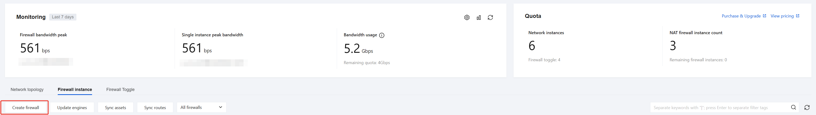
2. On the VPC Firewall (Primary/Secondary) page, click Firewall instance to go to the Firewall Instances page, and then click Create Firewall.
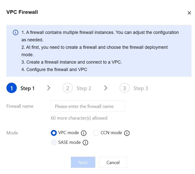
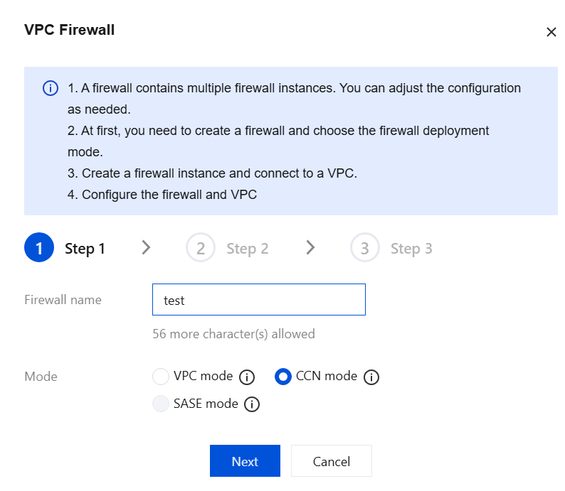
3. In the Create VPC Firewall dialog box, enter an instance name, select VPC Mode, and then click Next.
Parameter description:
Firewall Name: Indicates the name customized when you create a firewall instance.
Mode:
VPC mode: Select a VPC to connect to the firewall. Route steering is achieved by modifying the route tables of the relevant VPCs.
CCN mode: Select a CCN to connect to the firewall (multi-route table mode must be supported). Route steering is achieved by modifying the CCN route tables.
SASE mode: This feature is currently in a limited-time internal beta. To use it, submit a ticket.
VPC mode(CDC): It is consistent with the standard VPC Mode and is available only in CDC environments.
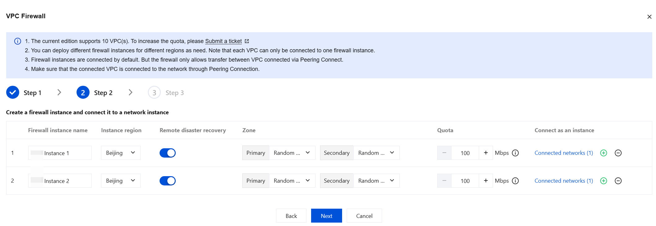
4. Enter the firewall instance name and region, configure disaster recovery information, set the bandwidth specification and access network for the firewall instance, and then click Next. If the number of instances does not meet your requirements, you can click
on the right to create multiple firewall instances.
Parameter description:
Instance Region: Select the region where the VPC to be protected is located.
Remote disaster recovery: The VPC Firewall supports cross-region disaster recovery. You can enable it by selecting the corresponding option.
Zone: Select an availability zone as needed.
Quota: A single instance currently supports a minimum of 100 Gbps and a maximum of 2296 Gbps. Upgrade and scale out is supported. If the maximum bandwidth is insufficient, you can create multiple firewall instances for traffic distribution. Note that each firewall instance has its own throughput limit. When using multiple instances, ensure that each individual instance operates within its throughput limit.
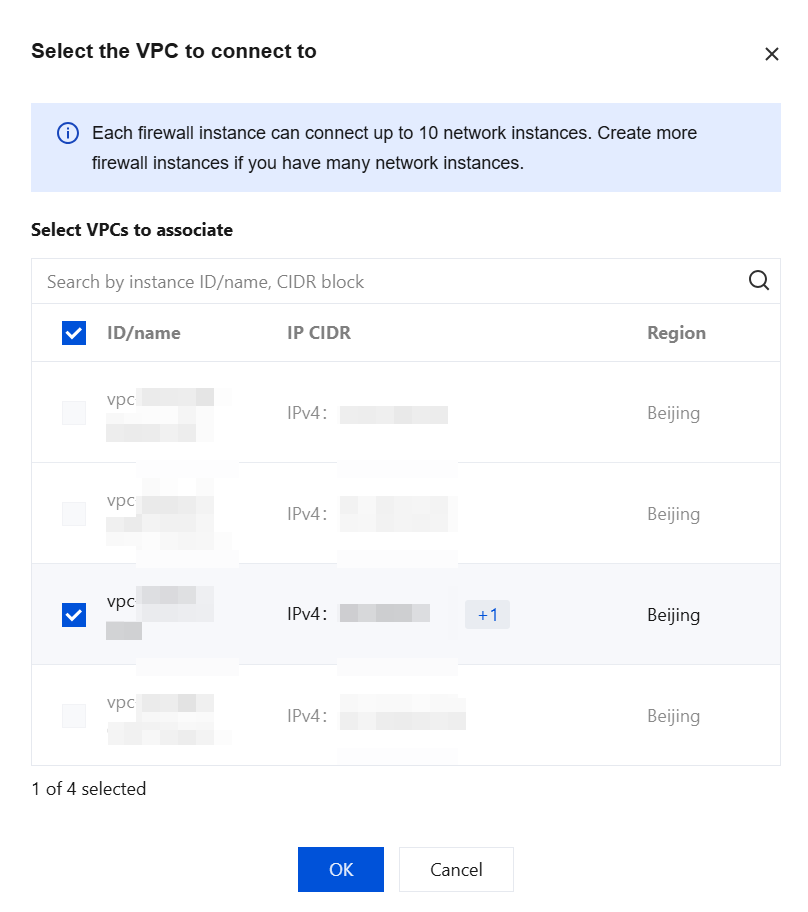
Connect as an instance: Click Connected network. Based on the region of the VPC you want to connect to, select the required VPC, and then click OK.
Note:
A VPC can connect to only one firewall instance.
The firewall cannot establish basic network connectivity. Before accessing the network, ensure that a Peering Connection/CCN has been created between the VPCs. If no connection is established between the VPCs, the access will not take effect, and the Firewall Toggle will not be available.
An Inter-VPC Firewall instance allows up to 10 VPCs in the same region, and you can create multiple instances in the same region. It is recommended to plan the VPCs to be connected according to regions in advance before creating firewall instances and accessing the network.
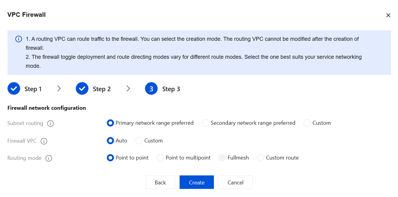
5. Configure the traffic redirection subnet method, firewall VPC, and routing mode. After confirming the settings are correct, click Create.
Note:
Configuration is complete. The creation process will take several minutes. Please wait patiently.
Parameter Name
Description
Subnet routing
CFW creates a /24 subnet in the connected VPC to route traffic to the firewall in different ways. Once the routing subnet is created, it cannot be modified.
Primary network range preferred: CFW automatically selects an idle subnet IP range in the selected VPC. If the VPC has no subnet quota, an extended IP range in the VPC is used.
Secondary network range preferred: CFW will prioritize using the idle expansion IP address range reserved for the VPC. This mode does not consume the subnet quota of the selected VPC. An expansion IP address range is an auxiliary IP address range within a VPC. For details, see Editing IPv4 CIDR Blocks.
Custom: You can only specify a /24 subnet within the CIDR block of the current VPC, such as 192.168.0.0/24.
Firewall VPC
It is used to connect firewall instances. You need to create firewall VPCs respectively in the regions where the selected VPCs are located.
Auto: CFW automatically creates a VPC with a /20 IP range that does not conflict with the connected VPCs.
Custom: You can enter a VPC with a /20 IP range that does not conflict with the planned network, such as 192.168.1.0/20.
Routing mode
The routing scheme of a firewall toggle. The way that networks are interconnected determines the specific firewall toggle and routing mode. It is recommended to choose a routing mode based on the workload network mode.
Point to point: It is suitable for scenarios where a few VPCs need to be connected and the network topology is simple. In this mode, one firewall toggle is generated for each VPC-to-VPC connection.
Point to multipoint: It is suitable for scenarios where multiple VPCs need to be connected and the network topology is simple, such as a star network topology. In this mode, one toggle is configured for each VPC, and traffic between two VPCs passes through two firewall toggles.
Fullmesh: It is suitable for scenarios where many VPCs need to be connected and the network topology is complex, such as a mesh network topology. In this mode, only one firewall toggle is configured to control all VPC routes.
Custom route: You can refer to the document Custom Routing Configuration Guide to configure routes yourself after creating the firewall. In this mode, no Firewall Toggle exists.
Note:
After multiple regions are selected, only custom routing is supported. For the availability of specific routing modes, refer to the console.
CCN Mode
Note:
Starting July 1, 2023, CCN will charge for network instances and inbound traffic processing. CFW requires you to create a dedicated firewall VPC for traffic steering within your connected CCN instances, which may incur costs. For details, see Start Charging on CCN Connected Network Instances and Inbound Traffic.
1. Log in to the CFW console, and in the left sidebar, choose Firewall Toggle > VPC Firewall (Primary/Secondary).
2. On the VPC Firewall (primary/secondary) page, click Firewall Instances to go to the Firewall Instances page, and then click Create firewall.
3. In the Create VPC Firewall dialog box, enter an instance name, select CCN Mode, and then click Next.
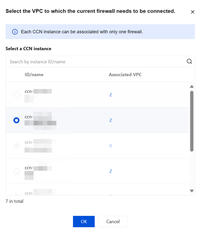
4. Click Click to Select. Then, based on the prompts, select the CCN instances to be added to the VPC Firewall, and click OK.
Note:
The CCN instances must support the multi-route table mode. If this requirement is not met, contact CCN to enable the multi-route table feature first.
In CCN mode, you can create a VPC Firewall in a specified region.
In CCN mode, a firewall can be bound to only one CCN instance.
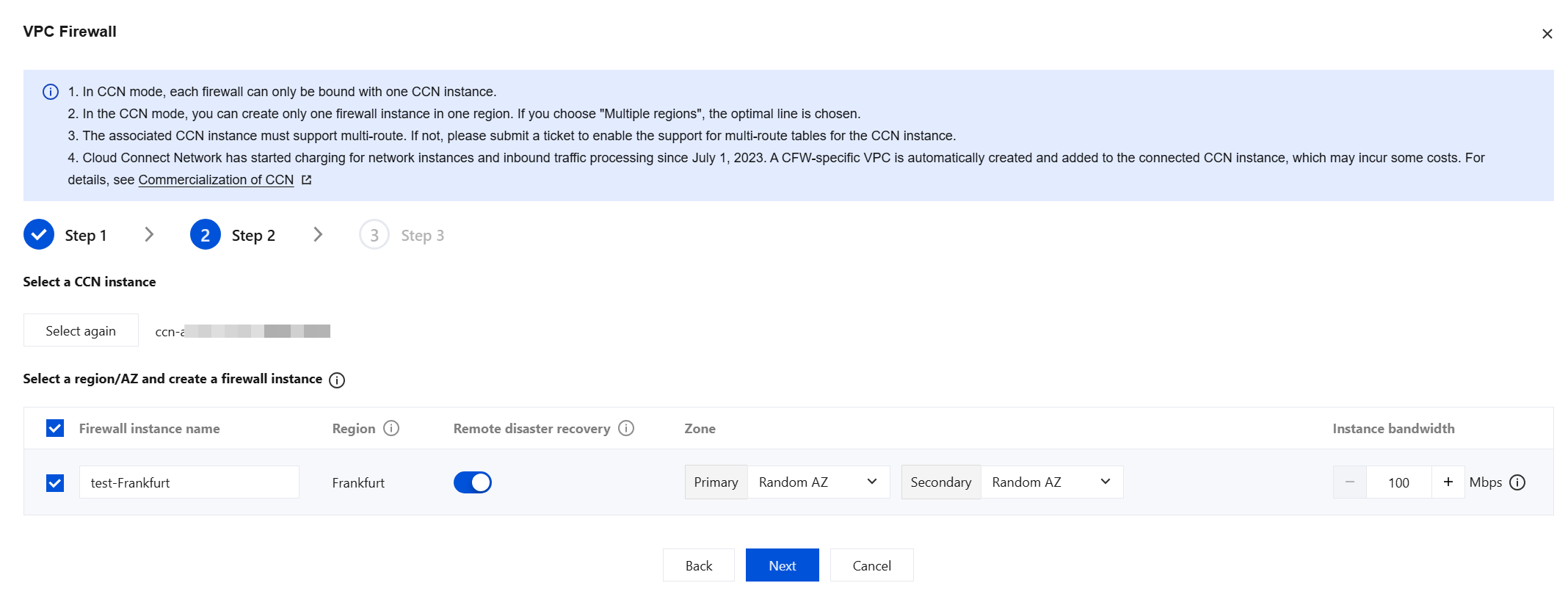
5. After you select CCN instances, the available regions are automatically generated below based on the VPCs connected to the CCN. If you select a region, a firewall instance is created in that region. You can configure the firewall instance name, whether to enable cross-region disaster recovery, and the instance bandwidth specification. Then, click Next.
Parameter Description:
Region: Select the region where the VPC to be protected is located.
Note:
If you select only one region to deploy a firewall instance, all traffic between VPCs with the Firewall Toggle enabled is routed through the firewall instance in that region. This configuration is suitable for business networks with a star topology.
If you select all regions to deploy firewall instances, all traffic between VPCs with the Firewall Toggle enabled is routed through the firewall instance in the local region. This configuration is suitable for business networks with a mesh topology.
After you select multiple regions, only custom routing is supported.
Remote disaster recovery: The VPC Firewall supports cross-region disaster recovery. You can enable it by selecting the corresponding option.
Zone: Select an availability zone as needed.
Instance bandwidth: A single instance currently supports a minimum of 100 Gbps and a maximum of 5320 Gbps. Upgrade and scale out is supported. If the maximum bandwidth is insufficient, you can create multiple firewall instances for traffic distribution.
Note:
Each firewall instance has its own throughput limit. When using multiple instances, ensure that each individual instance operates within its throughput limit.
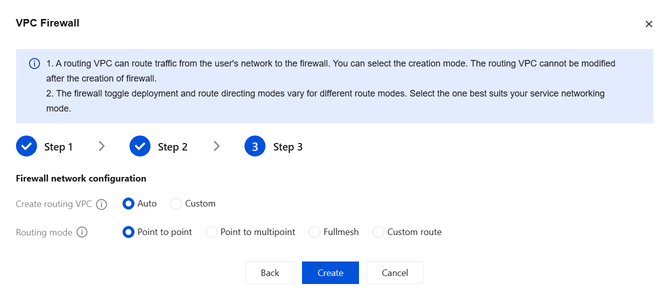
6. Configure the new traffic steering VPC and routing mode. After confirming the settings are correct, click Create.
Note:
Configuration is complete. The creation process will take several minutes. Please wait patiently.
Parameter Name
Description
Create routing VPC
CFW creates a /20 VPC in the selected CCN instance for traffic steering to the firewall. You can choose different methods to create the VPC.
Auto: CFW automatically probes for 20 idle VPC CIDR blocks for firewall traffic steering.
Custom: You can customize the VPC subnet for the firewall. Note that it must be a /20 subnet, for example, 192.168.1.0/20.
Routing mode
The routing scheme of a firewall toggle. The way that networks are interconnected determines the specific firewall toggle and routing mode. It is recommended to choose a routing mode based on the workload network mode.
Point to point communication: It is suitable for scenarios where a few VPCs need to be connected and the network topology is simple. In this mode, one firewall toggle is generated for each VPC-to-VPC connection.
Point to multipoint: It is suitable for scenarios where multiple VPCs need to be connected and the network topology is simple, such as a star network topology. In this mode, one toggle is configured for each VPC, and traffic between two VPCs passes through two firewall toggles.
Fullmesh: It is suitable for scenarios where many VPCs need to be connected and the network topology is complex, such as a mesh network topology. In this mode, only one firewall toggle is configured to control all VPC routes.
Custom route: You can refer to the document Custom Routing Configuration Guide to configure routes yourself after the firewall is created. In this mode, no Firewall Toggle exists.
Note:
After multiple regions are selected, only custom routing is supported. For the availability of specific routing modes, refer to the console.
Instance Specifications
VPC Firewall Instance Specifications Tier Table.
Note:
VPC Firewall instance specifications and private network rule list quotas are independent of each other, unrelated to billing logic, and cannot be scaled out separately. They can only be upgraded by enhancing the instance specifications. For each ACL configured in the console, we automatically convert it into specific rules according to the deployment formula, identify the source and destination, and deploy them to the specified VPC Firewall instance.
Deployment formula: Number of deployed rules = Number of source addresses × Number of destination addresses × Number of ports × Number of protocol types.
The VPC Firewall instance specification determines the maximum number of ACL rules each VPC Firewall instance can handle. Deploying an excessive number of ACL rules may cause engine instability.
To avoid impacting your business operations, we recommend optimizing rules based on each instance's specifications and the number of deployed rules, reducing the proportion of redundant rules to enhance engine stability.
Specification Tiers
Minimum Bandwidth/Mbps
Maximum Bandwidth/Mbps
Concurrent Connections/Unit
Number of Rules Quota / Item
1
100
1,023
130,000
5,000 (Intrusion Defense feature not included in this tier).