The NAT Firewall (Cluster Mode) is a north-south traffic protection capability provided by CFW. It performs unified detection and Access Control on traffic from multiple business VPCs accessing the internet via NAT Gateways through CCN. This helps users centrally defend against attacks from the internet and manage unauthorized outbound connections from cloud assets.
In Manual Connection mode, CFW only automatically creates the basic resources required for traffic steering, such as the traffic diversion VPC and GWLB endpoints. Route configuration must be manually completed on the CCN console to direct business traffic to CFW for inspection. If route configuration is not completed, traffic will not pass through the firewall even if the Firewall Toggle is enabled, and the protection capability will not take effect.
Notes:
This document applies only to the manual connection - multi-route table scenario for the NAT Firewall (Cluster Mode).
Prerequisite
You have enabled the Firewall Toggle and configured traffic steering in CFW console > NAT Boundary (Cluster), and selected multiple-route table as the manual access method. For details, see Firewall Toggle.
The VPC where the NAT Gateway resides, the business VPCs requiring protection, or the Direct Connect gateways have been associated with the same CCN instance.
CFW has successfully created the dedicated VPC for NAT firewall traffic steering and the GWLB endpoint.
Confirm the business network segments that require protection by CFW, such as business VPC CIDR blocks or Direct Connect side segments.
It is recommended to perform the route switching operation during off-peak business hours or within the change window.
Configuring Route Traffic Steering to CFW
Step 1: Confirm the Dedicated VPC for NAT Firewall Traffic Steering Is Created
1. Log in to VPC console, in the left sidebar, click Cloud Connect Network.
2. In the CCN instance list, click the ID/Name of the target CCN instance.
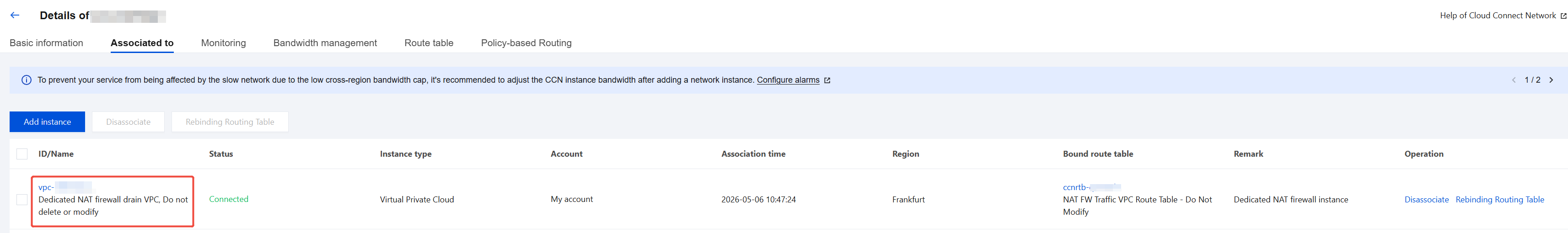
3. In the Associated to tab, check whether there is a VPC instance named Dedicated NAT firewall drain VPC, Do not delete or modify with its status as Connected. If it exists, this indicates that the firewall traffic steering VPC has been successfully created.
Notes:
If the traffic diversion VPC or related routing tables have not been created, please wait a moment. If the process is not completed after a long time, please submit a ticket to contact us.
Step 2: Configure Routing Policy
This step consists of two parts:
Configure Traffic Steering Route: Direct business traffic from the traffic diversion VPC to the firewall gateway cluster.
Configure Return Traffic Route: Forward the return traffic inspected by the firewall back to the business VPC, ensuring that both inbound and outbound traffic passes through the firewall.
2.1 Configuring Traffic Steering Route
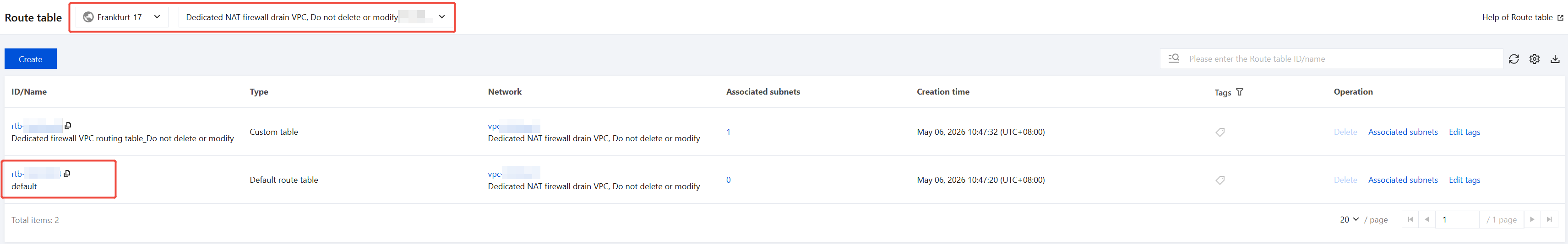
After the traffic diversion VPC is created, the system automatically generates a routing table named default under this VPC. In this routing table, you need to disable the existing 0.0.0.0/0 default route with the next hop set to CCN and add a new 0.0.0.0/0 default route with the next hop set to the GWLB endpoint. This directs traffic entering the traffic diversion VPC to the CFW gateway cluster.
1. Go to the VPC > Routing Tables > Routing Tables page. At the top, select the region where the traffic diversion VPC is located, and then switch to the traffic diversion VPC.
2. In the routing table list, select the default routing table, then click Basic information to go to the details page.
3. Locate the existing 0.0.0.0/0 route with the next hop pointing to CCN, and click
to disable it.
Notes:
This entry is disabled to prevent it from conflicting with the newly added route. Keeping the original route would cause traffic to be forwarded directly through CCN, bypassing firewall inspection.
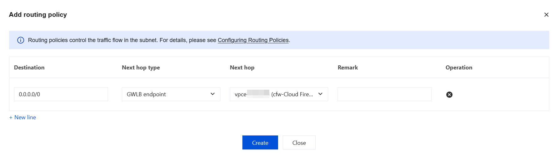
4. Click Add routing policy, configure it with the following parameters, then click Create to set the next hop for all outbound traffic to the firewall:
Destination: Enter 0.0.0.0/0
Next hop type: Select GWLB endpoint
Next hop: Select the GWLB Endpoint corresponding to the NAT firewall gateway. This endpoint is automatically created by the system when the Firewall Toggle is enabled.
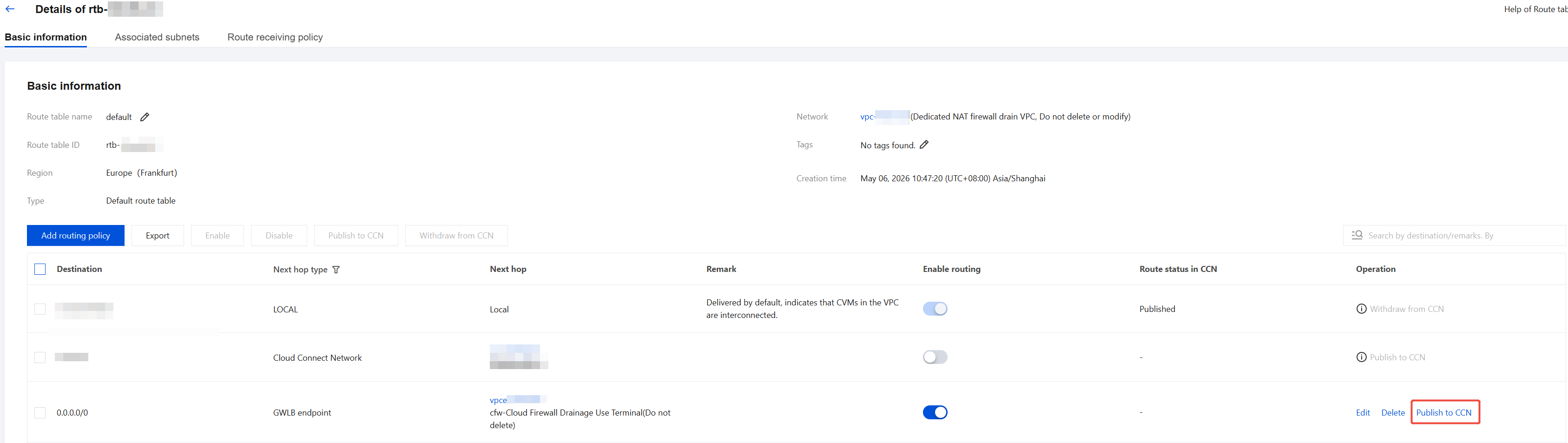
5. Return to the Routing Table Basic Information page, select the newly added routing policy, and click Publish to CCN.
Notes:
Because the CCN route acceptance policy is not yet configured (this will be completed in Create a CCN Routing Table and Bind Network Instances ), the newly published route will appear as Invalid on the CCN side. This is normal. After Step 3 is completed, the route will automatically take effect, requiring no manual intervention.
Configuring Return Route
This operation configures the routing table system-auto-for-nat-ccn of the VPC to which the NAT Gateway belongs. This configuration enables return traffic from the NAT Gateway to be forwarded to the firewall via CCN, thereby ensuring that both inbound and outbound traffic passes through the firewall.
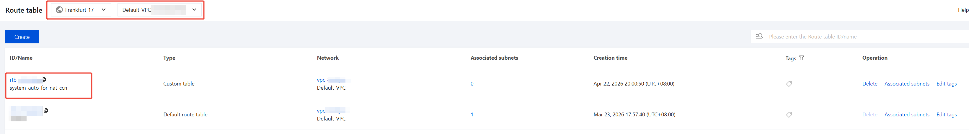
1. Go to the VPC > Routing Tables > Routing Tables page. At the top, select the region where the VPC of the NAT Gateway is located, and then switch to that VPC.
2. In the routing table list, select the system-auto-for-nat-ccn routing table, then click Basic information to go to the details page.
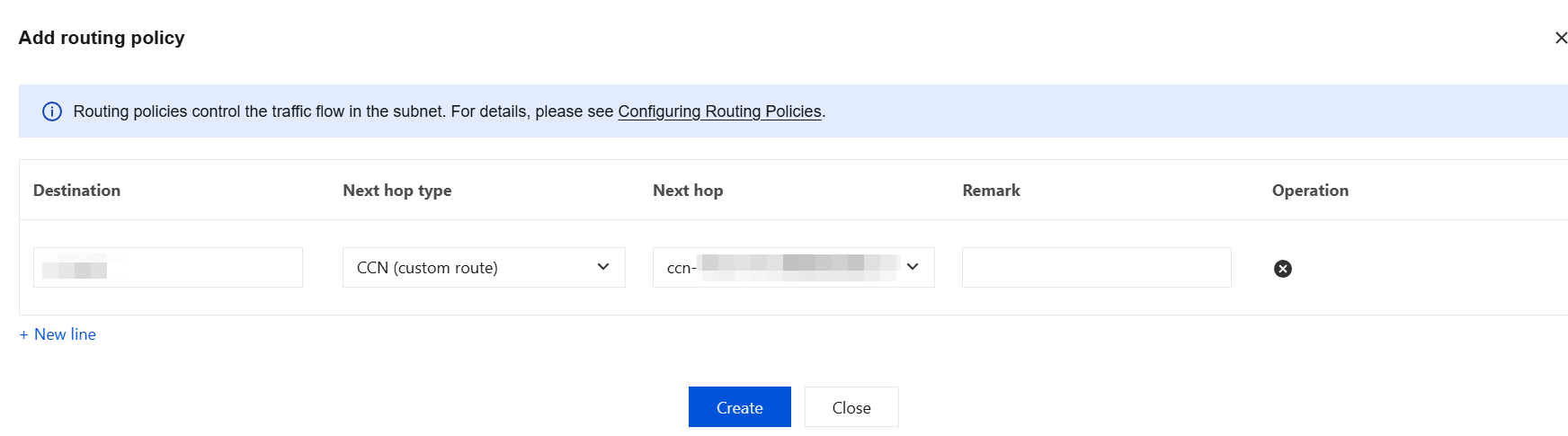
3. Click Add routing policy, configure it with the following parameters, then click Create to forward return traffic to the destination business VPC:
Destination: Enter the CIDR of the business VPC.
Next hop type: Select CCN (custom route).
Next hop: Select the ID of the currently used CCN instance.
Note:
If a newly added route overlaps with or contains an existing route, disable the contained specific route accordingly. Because CCN follows the Longest Prefix Match principle, the specific route with a longer mask takes precedence. The newly added summary route will only take effect for addresses not covered by the specific route and cannot take effect uniformly for the entire target network segment.
Step 3: Create CCN Routing Tables and Bind Network Instances
This step establishes a communication path between the firewall traffic steering VPC and the business VPC by creating a new routing table and configuring a route acceptance policy in CCN, while preventing interference between the two types of traffic.
3.1 Creating Routing Tables
1. Go to the VPC > Cloud Connect Network page. In the CCN instances list, click the ID/Name of the target CCN instance to go to its details page.
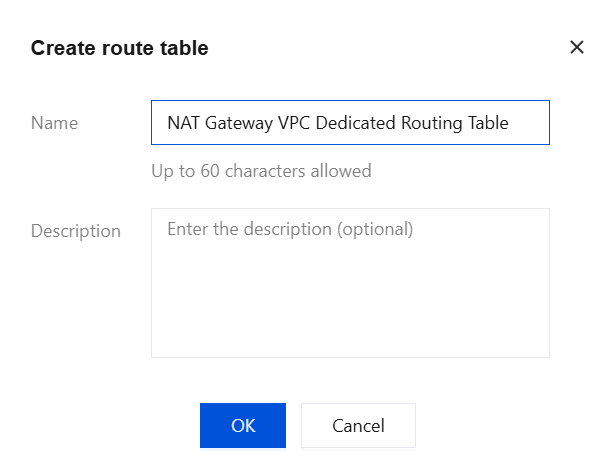
2. Switch to the Routing Tables tab, then click Create Routing Table.
3. Create a routing table for the NAT Gateway VPC (it is recommended to name it "NAT Gateway VPC Dedicated Routing Table"), then click OK.
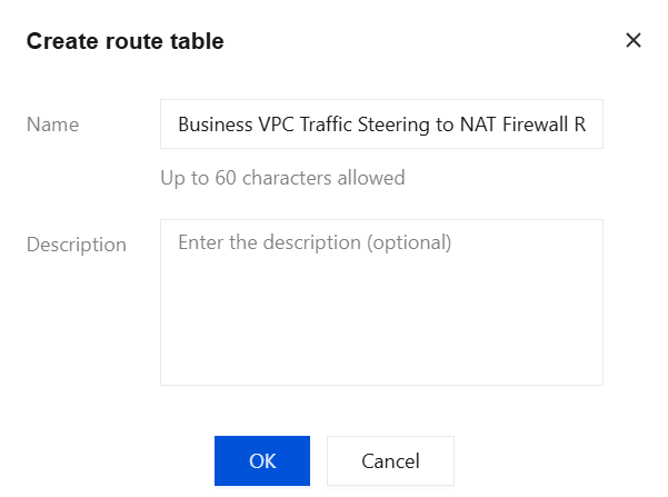
4. Create one or more routing tables for the network instances (VPC or Direct Connect Gateway) that need to connect to the NAT firewall (it is recommended to name them "Business VPC Traffic Steering to NAT Firewall Routing Table"), then click OK.
3.2 Adding a Route Acceptance Policy
A route acceptance policy controls which network instances each routing table receives routes from. You need to add two policies for each of the two routing tables mentioned above.
The two routing tables are assigned the following roles:
NAT Gateway VPC Dedicated Routing Table: Receives routes from the business VPC and the firewall traffic steering VPC, enabling the NAT Gateway to correctly send return traffic back to the business side.
Business VPC Traffic Steering to NAT Firewall Routing Table: Receives routes from the NAT firewall traffic steering dedicated VPC, enabling business traffic to be steered into the firewall for inspection.
3.2.1 Adding a Policy to the NAT Gateway VPC Dedicated Routing Table:
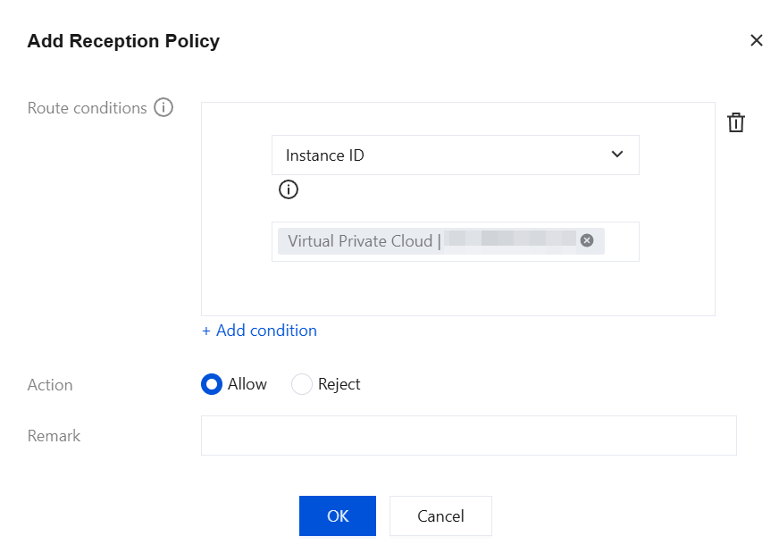
1. Select the NAT Gateway VPC Dedicated Routing Table, switch to the Route receiving policy tab, then click Add policy.
2. Under Condition, when you select Instance ID, add the network instances in the current CCN that are not involved in this NAT firewall protection. Specifically, these are the other VPC instances remaining after excluding the VPC where the NAT Gateway resides, the dedicated VPC for NAT firewall traffic steering, and the business VPCs or Direct Connect Gateways that need to access the public network through this NAT Gateway and be protected by CFW, from the instances currently associated with the CCN.
3. For Action select Allow, then click OK.
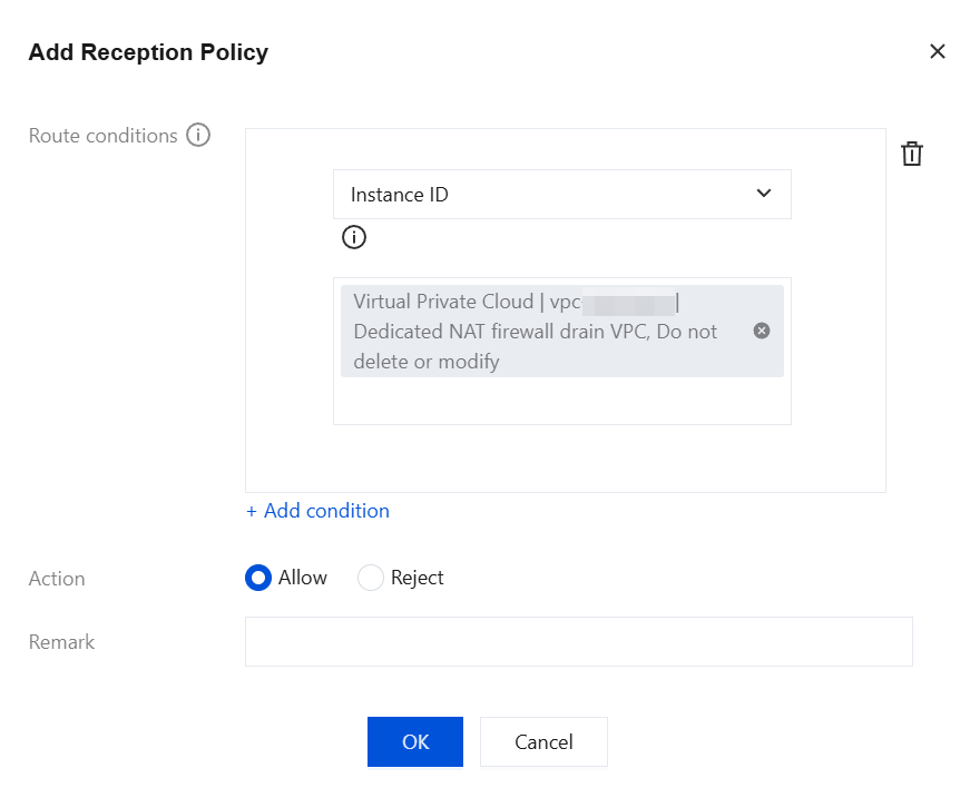
4. Click Add policy again. Under Condition, select Instance ID to add the NAT firewall traffic steering dedicated VPC instance.
5. For Action, select Allow, then click OK.
3.2.2 Adding a Policy to the Service VPC Traffic Steering to NAT Firewall Routing Table:
1. Select the Business VPC Traffic Steering to NAT Firewall Routing Table, switch to the Route receiving policy tab, then click Add policy.
2. Under Condition, select Instance ID to add the NAT firewall traffic steering dedicated VPC instance.
3. For Action, select Allow, then click OK.
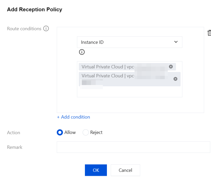
4. Click Add policy again. Under Condition, select Instance ID to add all business VPC instances except the NAT firewall traffic steering dedicated VPC.
5. For Action, select Allow, then click OK.
3.3 Binding Network Instances
Note:
Before binding a network instance, traffic follows the original routing table. After the network instance is bound, network traffic is immediately steered to the firewall, with no secondary confirmation step. Before binding, ensure that the preceding route configuration is correct, otherwise service interruption may occur.
During the binding process, an intermediate state where some traffic passes through the firewall first may occur, which is expected. Complete all binding steps consecutively before performing service validation.
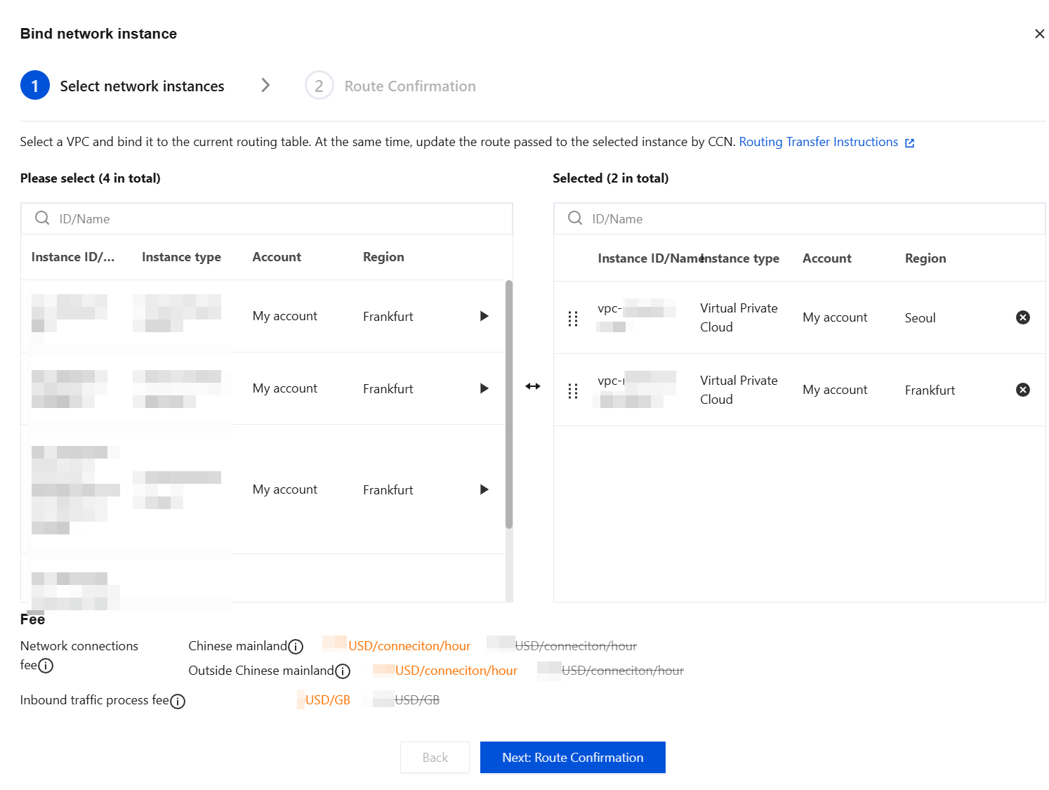
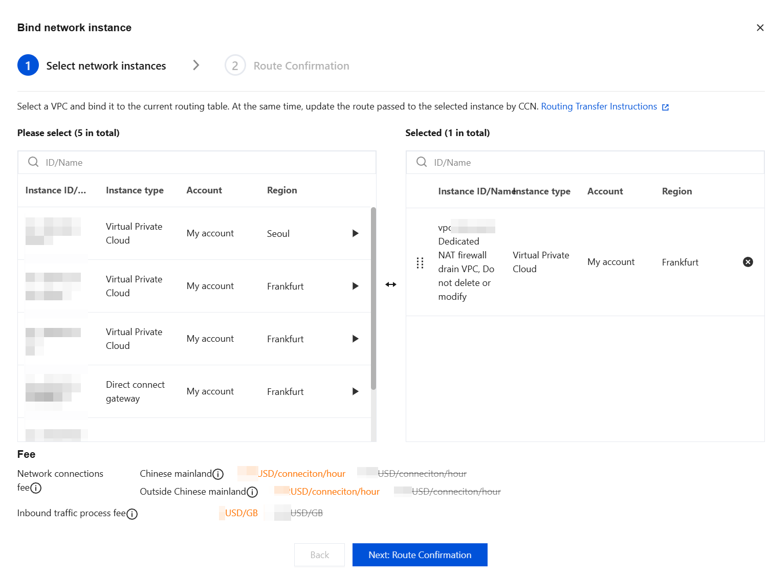
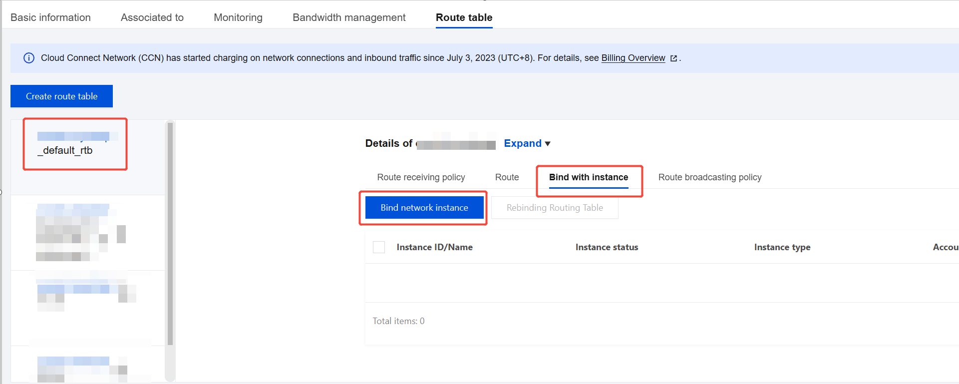
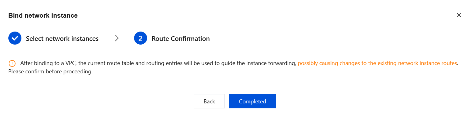
1. Select the Business VPC Traffic Steering to NAT Firewall Routing Table, switch to the Bind with instance tab, then click Bind network instance.
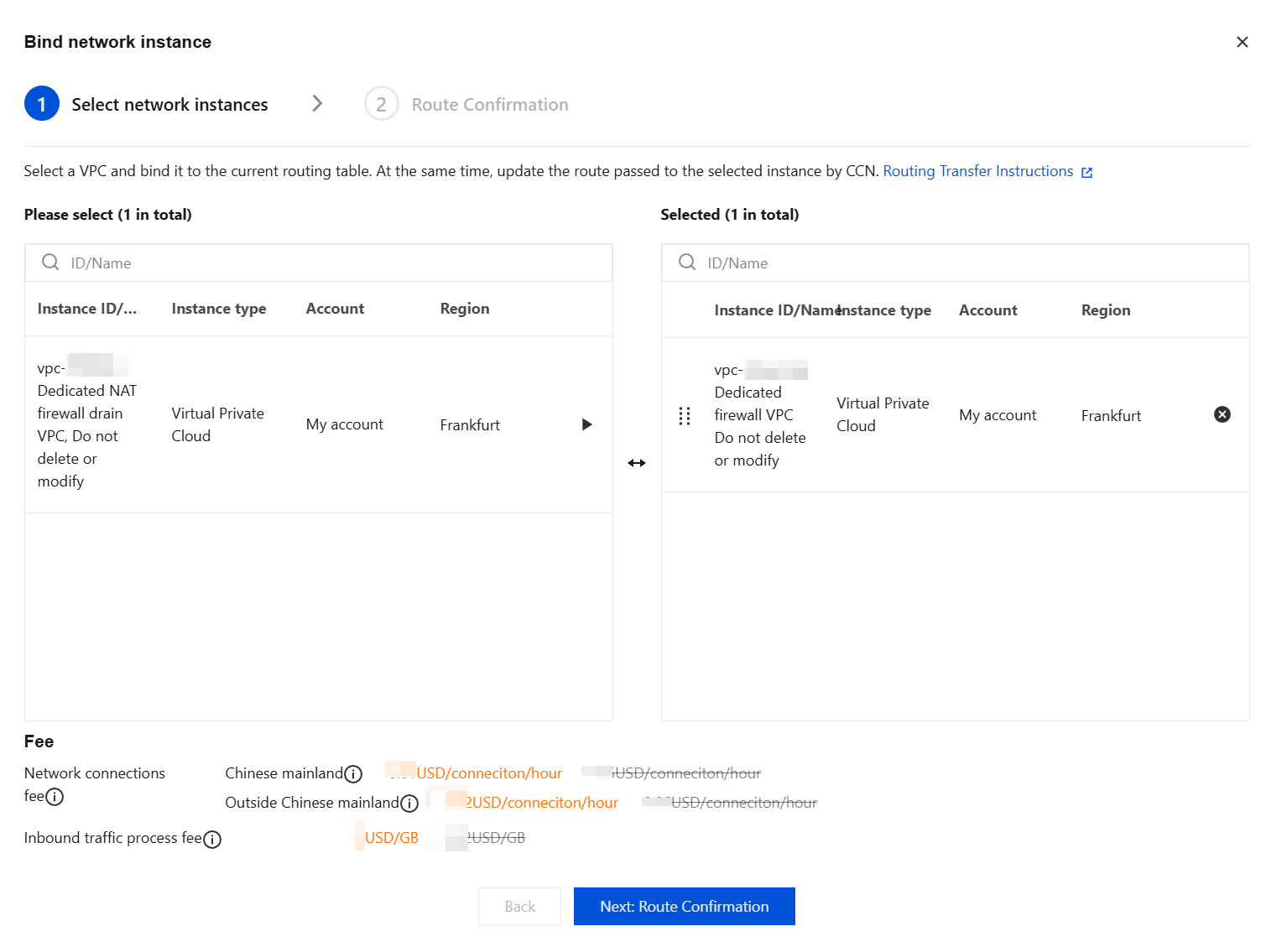
2. Select the network instances that need to be connected to the NAT firewall, click the corresponding option
, and after the selection is complete, click Next: Route Confirmation.
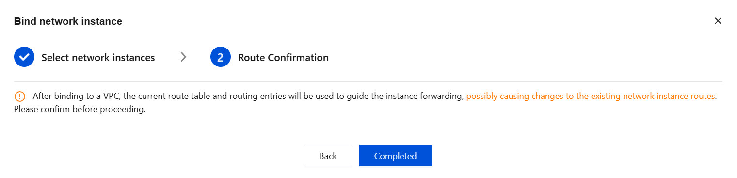
3. After the route information is verified to be correct, click Completed.
4. Select the NAT Gateway VPC Dedicated Routing Table, switch to the Bind with instance tab, then click Bind network instance.
5. Select the network instance of the VPC to which the NAT Gateway belongs, click the corresponding option
, and after the selection is complete, click Next: Route Confirmation.
6. After the route information is verified, click Completed.
Step 4: Verifying Firewall Access
1. Log in to the CFW console. Refer to Log Auditing to check whether there are traffic logs for the relevant business, verifying whether traffic passes through the firewall.
2. Refer to Log Auditing to check whether Intrusion Defense is functioning normally.
3. Configure the NAT Border Rule and check whether it is triggered normally.
The firewall is now functioning normally. If your network architecture is complex or involves dedicated line scenarios, please submit a ticket to consult on detailed routing configuration solutions. For any further questions, you are also welcome to submit a ticket to contact us.
Configuring Routes to Disable Traffic Steering to CFW
1. Log in to VPC console, in the left sidebar, click Cloud Connect Network.
2. Go to the console of the CCN instance for which you need to disable the NAT Firewall, and view the details of the CCN instance associated with the multi-route table mode protection object.
3. Bind all network instances, except for the firewall-dedicated VPC, to the routing table that was used before they are connected to the CFW.
3.1 Select the routing table that was used before you connect to the CFW, typically the _default_rtb table, then choose Bind Instance > Bind Network Instance.
3.2 Select all instances except those dedicated to the firewall.
3.3 Confirm the routes, then click Completed.
4. After it is verified that the network is functioning normally, disable the Firewall Toggle corresponding to the current NAT Gateway in the CFW console.
Note:
Ensure that the instance has been disconnected from the CFW before you disable the corresponding NAT Firewall Toggle. Otherwise, network interruption may occur.